Latest Posts

Sunday, December 28, 2014

Final Robot Design

Purpose 

The purpose of this post is to reflect on the finished design, so that we can identify what worked and what didn't work in our robot.

Final Design

In our final design, we opted for a much simpler design. The robot was told to follow the walls of the field until an Infrared Beacon (2kHz) was detected, at which point the robot would follow up with its crown grabbing routine. When the robot obtains the crown, the robot proceeds to follow the walls back to its home castle. 

Finding Home

The robot is able to find its home castle, because it knows that the starting castle is 4 castles away from its home castle.

Counting Castles

To effectively count castles, we had to use the robot's internal timeout (a period in which no bump or tape sensors triggered an event) to effectively count the new location as a new castle. After 4 new castles are detected, the robot would declare the current castle as its home castle and it would proceed to drop the crown on the throne. A diagram of the robot's operation is shown below:

Conclusion

From our initial design, it's very obvious that we modified much more than a few things. Our robot's operation is much simpler, and we managed to get checked off with our current design. A video of the checkoff is shown below:

Wednesday, December 10, 2014

50kHz Beacon and Detector Circuits

Background

The Beacon detector that we had built prior to the design of our robot was built with the intention of detecting an infrared signal at a 2kHz frequency. The filters were modified and specially designed such that the detector could accurately detect the 2kHz frequency and block out lower frequencies (Resonant frequency, 60Hz monitors in lab, etc). The filter had to also block out much higher frequencies as well - sunlight is composed of many different wavelengths of light. 

Summary - we need to  locate the light source (signal) we want to see and ignore (filter) any light sources we don't want to see.

Purpose

The plan for the extra beacon is to have a way for the robot to return home. In a nutshell, we can reverse our robot's operation of getting to a castle to going home from the castle (return back to the home castle which we started). Using a second beacon detector - adjusted so that it can detect the 50kHz frequency IR signal.

It is not necessary, but it is the easiest and most effective way for us to get home to our castle. Preliminary testing of our beacon detector for an IR signal of 50kHz were very promising - we achieved a range of 3 meters total each time.

50kHz IR Beacon 

Limitations

Our IR Beacon was approved by the professor under the conditions that 
  • IR Beacon must operate within a frequency (f) of the range 40kHz < f <100kHz

Results

We decided to create the beacon ourselves, as most of the parts were already provided to us in the lab. I found some 555 timers left over, so I decided to work on creating the circuit by using the 555 timer in astable mode to produce a dc waveform with a frequency defined by the resistors and capacitors in series. The 'high' times of the signal waveform are defined by:


Thus, the values chosen to produce the required waveform were : 
  • C1 = 22 nF
  • R1 = 560 Ohms
  • R4 = 100 Ohms

I mainly chose these values because I was supplied a 22 nF capacitor in our parts kit, and the resistors were adjusted accordingly. 
  • calculated frequency of the DC waveform is 53.76 kHz, the actual waveform turned out to be around 54.21 kHz. 
ABOVE: Output waveform of the 555 timer circuit in \
Astable Operation with the component values shown above.

Circuit Diagram


Results

We tested each of our components (IR LEDs) in the circuit to ensure that the waveform generated was correctly read by the IR Phototransistor circuit below:


Saturday, November 29, 2014

Sensor Modules

Purpose

The Purpose of this post is to identify the many ways we will be interfacing with the hardware sensors that we have chosen to use within our robot. The interface with the sensors is all done through the Arduino Due. 

Ultrasonic Distance Sensor

At the start of the operation of our robot, we decided to perform a sweep of the room in which our robot turns 360 degrees and searches for the longest distance (sensor maxes out at around 4m). 
Our robot checks the current Radial Direction of our bot and utilizes a proximity sensor to perform a ‘sweep’ of the room. The robot is essentially searching for an opening, meaning that the output signal of the proximity sensor’s echo pin must remain high for a certain length of time.
If we are searching for a certain 'length of time' and our PIC32 is only allotted a limited number of I/O Ports, we must determine the most cost-effective (money and time) to develop a system of checking for a high pulse out of the ‘echo’ pin on the Proximity Sensor.
 The Ultrasonic Distance Sensor works by sending out a 10 microsecond TTL pulse on the trig port, sends out 8 40kHz sonic bursts, then sets the output echo port high and awaits a returned Ping. The diagram of the module is shown below, and the probed outputs created are shown to the right and below. 

The most important factor influencing the speed of sound in air is temperature.  The speed is proportional to the square root of the absolute temperature. The speed increases at about .6m/s per degree[1].

 To calculate the sensor feedback, the module was elevated off the ground and stabilized using some foam core scraps. See the 'SensorBot' above.

The code for the proximity sensors were found through the GitHub account of one of the original designers of the module. The only changes I made were converting the inches into cm - in an attempt to keep uniform units across sensor inputs:


/* ProximitySensorFeedback() - this function interfaces directly with the
proximity sensor and returns a 16-bit value corresponding to the distance in mm
The speed of sound is 340 m/s or 29 microseconds per centimeter.
The ping travels out and back, so to find the distance of
the object we take half of the distance travelled.*/
long ProximitySensorFeedback(int ping, int echo)
{
  // establish variables for duration of the ping,
  // and the distance result in inches and centimeters:
  long duration, centimeters;
  int currentDist;
  // Give a short LOW pulse beforehand to ensure a clean HIGH pulse:
  digitalWrite(ping, LOW);

  delayMicroseconds(2);
  digitalWrite(ping, HIGH);
  // pulse whose duration is the time (in microseconds) from the sending
  delayMicroseconds(5);   digitalWrite(ping, LOW);   // of the ping to the reception of its echo off of an object.   duration = pulseIn(echo, HIGH);   // convert the time into a distance   centimeters = duration / 29 / 2;   return centimeters; }

Beacon Detector

The IR Beacon with the crown is easily located through the IR Beacon Detector by a range of approximately 10 feet. The caveat here is that the beacon detector must be dead set on the beacon to actually detect it. Thus, a short radial sweep will be required when looking for the 2 kHz Beacon at the initial start of the robot's operation.
The second IR Beacon Detector will be searching for a beacon at the 56 kHz frequency (our daughter beacon). With the second beacon detector we can detect the daughter beacon that will be located at our home castle. Thus, we have effectively created a discernible IR Beacon that we can use to follow our way back home.
The Second Beacon Detector will require high pass filtering to only detect an IR beacon at the higher frequency.


[1] This also makes quite a good argument for utilizing ambient temperature feedback, but the cost of the module outweighs the benefits (the precision of the distance feedback required).

Hierarchical State Machine

Purpose

The Purpose of this post is to outline the final Hierarchical State Machine  that will be implemented within our robot's software. A hierarchical state machine differs from a typical finite state machine in that it allows for the programming of functions by difference (also known as software by inheritance). This allows us to define new classes based off old classes, and only specify the difference between the two modules. This also introduces behavioral inheritance - which, in our case, allows us to have similar states of operation for the robot. For example, the robot will be in an "open field" operation at least twice over the course of the challenge. Thus, it would save us a lot of time to declare this instance of operation with a single state "openFieldOperation"- defining the behavior as a function of the robot's sensor feedback.

HSM Highest Level of Operation


HSM - Lower Level 

Calibration


Friday, November 28, 2014

MarkII Bettle Design


After prototyping and drastic changes we have arrived at what will probably be the final design:


The support system for the scoop has changed to a single servo and a removable shaft on the other. This means that if the servo needs to be replaced all that needs to be done is remove the shaft, unscrew the horn through the shaft holes, and remove the scoop. 

The device on the back end is the mechanism for hooking a beacon onto the castle walls. It will be at a 45degree angle at start and will rotate down. The beacons frame should be as light as possible to not stress the servo shaft too much.


The "hook" has a ramp section towards the back so in case the bot doesn't reverse enough the beacon will still slide to the flat section where it is balanced. Most weight will be shifted back towards this ramped section so that the face will be as close to parallel with the wall as possible.

The layout of the field prevents this beacon from being placed outside of our castle so this will have to be placed on the back trackwire wall of our castle. If the beacon is bright enough we should be able to see it just like the thrown beacon, but that is what we need to test.

Monday, November 24, 2014

DC Motors and H-Bridge

DC Motors and H-Bridge

The DC motors we ordered are rated as 6 Volt motors with a stall current of 5 Amps.These motors were chosen because they provide a stall torque of 376 ounce-inches and an maximum RPM of 294.
Displaying photo.JPG
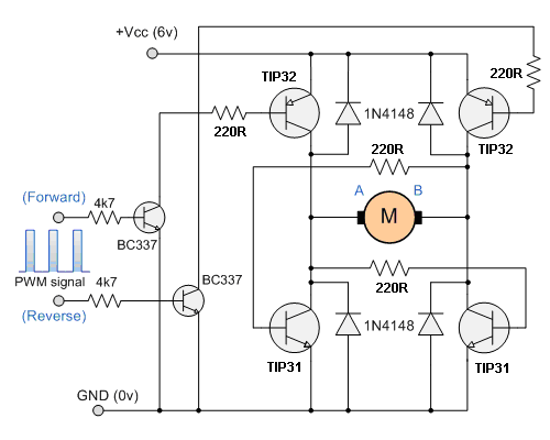
We found that the motors draw approximately 3.8 Amps of stall current with 5 Volts passing through them, giving them an internal resistance of about 1.3 Ohms. The current drawn by these motors are too much for the H-bridges provided, so we had to come up with a H-bridge design.

We found an H-Bridge design on the following website:
 http://www.talkingelectronics.com/projects/H-Bridge/H-Bridge-1.html

This model only supplied 3 Amps and we did not have the correct components to design this, so instead, we used the design structure to implement a new design using our own components. We could not get the top design working with the NTE2328's and NTE2329's, so instead we implemented the following design instead using the TIP 122's (NPN)and the NTE2328 (PNP):


This design powered the motor without a problem, but the issue with this new design was that in order to power the motors off, the input transistors essentially connected the base of the PNP's to ground, but the 10 Ohm resistor connected 5Volts to Ground. This made the design too unreliable, since the resistor was too hot. Experimentally, changing the resistor value to a higher value would make the motors slow down because it caused less voltage across the motor. To fix this, we changed out the PNP transistors with NTE2325's and used the same design as the one found from the website. 


Unfortunately, these transistors have a high Vce drop, so the motors were slow. The large voltage drop may have been due to the resistor values chosen, especially since they were not changed. We were going to calculate appropriate values, but luckily an  older H-bridge model was found and provided by Gabe.


Friday, November 21, 2014

Serial Communication Protocol between Boards

Purpose

The purpose of this post is to outline the choices we have regarding communication between multiple microcontrollers. Our current prototyped design requires 14 PWM I/O ports, an SPI port, and 4 ADC ports. This makes the use of the PIC32 a less feasible option for controlling our robot’s low- level operations. Therefore, we decided to use a second microcontroller to collect feedback data from the sensors and provide the data through to the main system board.

Choice of Microcontroller

We were only provided one board for the robot, so a second development board would have had to be purchased. In our case, our software lead had an Arduino Due that he was willing to part with.
The Due has 3 high resolution DAC Outputs that I was interested in using as a possible means of communication between the two boards.

P.Memory (Kbytes)
2048 Flash
P.Memory (KWords)
512
Self-Write Flash
Yes
RAM (Bytes)
512K
Auxiliary/Boot Flash
160
Emu. Flash
Yes
Dual Boot Flash Write
Yes
I/O Pins
120
Max CPU Speed
200 MHz (330 MIPS)
Internal OSC
8 MHz, 32 kHz
System Mgmt Features
8-DMAC, BOR, LVD, POR, WDT, RTCC, Osc <=1% accuracy
Analog Peripherals
2-Comparators, Bandgap - Yes; 1A/D, 48x ADC Mode-1 10-bit @ 500ksps; ADC Mode-2 0-bit @ 0ksps
Digital Comm. Peripherals
6-UART w/IrDA®, 6-SPI™, 5-I2C™, 6-I2S™, AC97, I2S
Connectivity
1-HS Device/Host/OTG-, 10/100 Base-TX Mac, LIN, IrDA
Digital Peripherals
9-Output Comp. PWM , 32-bit PWM, 9-Input Capture, PPS

Communication Options

Our choices of serial communication options were, at first, limited by the availability of certain I/O ports on either the PIC32 or the Arduino Due. After we had the opportunity to research more interfaces – we attempted a few of the more common communication protocols (I2C and SPI), but ran in to issues with the arduino spamming the input buffer of the PIC32.
We didn’t have a lot of time to find out why the SPI interface was not working, but we tried the sample code available on the microchip website and I tried probing  on the oscilloscope successfully, but I couldn’t configure the device in master mode properly.

Final Decision

We decided on creating our own communication system, because the options available on the Due (mainly UART and I2C, SPI, and CANBUS) did not match the simplicity of a hardcoded interface that we could create for this particular purpose. Also, both MCU’s have the same operating voltage, so we could communicate direct pinouts without any issues.


From Arduino to Pic32

  • 3 digital pins as input from the Pic32 for commands being sent (3 bit unsigned). 
  • 3 analog pins (up to 12 bit DAC) are used to send data from the arduino to the PIC32 upon request. 
  • voltage reference pin (labeled VREF onboard) is also wired to the 3.3V out of the PIC32
  • common Ground pin  

From Pic32 to Arduino

  • 3 ADC pins (Delta-Sigma, precise up to 10 bits)
  • 3 digital pins are used to send data to the Arduino from the PIC32 (treated as a 3-bit unsigned value)
  • voltage reference pin (3.3V works as well)
  • common Ground pin 

 Diagram of Serial Connections Required